|
SITE INDEX |


All about Amateur Television - ATV. Ham Radio with Vision
Hosted by Tom O'Hara W6ORG - Email:

Retired owner of P.C. Electronics, The Leader in Amateur Television Equipment for 50 years - history
Last update May 8, 2026
4 Channel ATV TCXO
|
All about Amateur Television - ATV. Ham Radio with Vision Hosted by Tom O'Hara W6ORG - Email: Retired owner of P.C. Electronics, The Leader in Amateur Television Equipment for 50 years - history Last update May 8, 2026 4 Channel ATV TCXO |
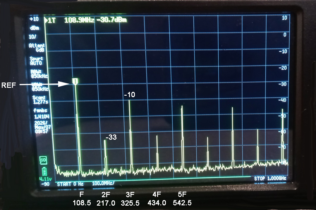
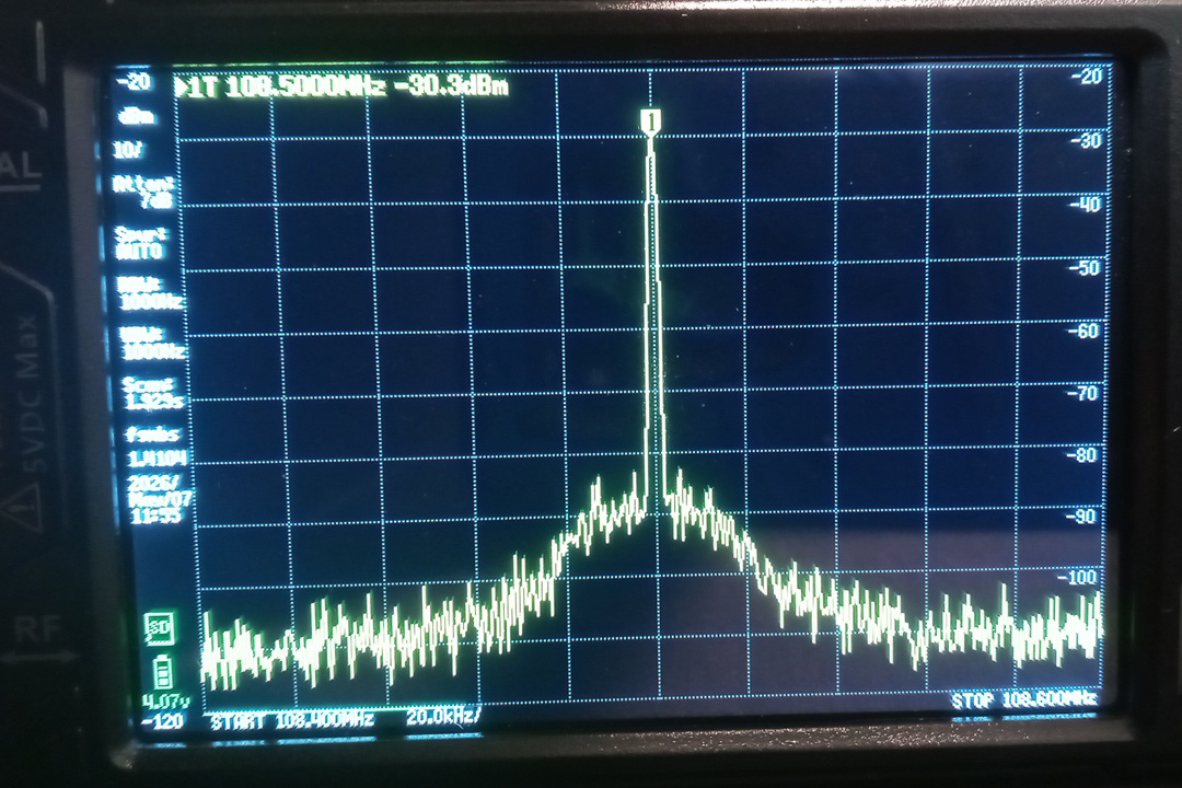
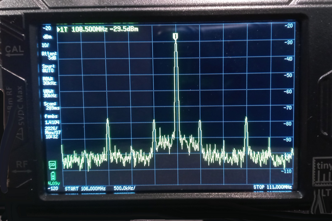
Crystal Substitute Project: This application note describes a low cost 4 channel TCXO substitution for crystals in our P. C. Electronics ATV gear. Most all our ATV transmitters have the same oscillator circuit using 5th overtone series resonant HC49 or HC50 crystals. There are very few crystal manufacturers these days and those that are around dont make the 5th overtones in the greater than 100 MHz region. Small temperature compensated crystal oscillators (TCXO) have been around, but the phase noise and spurs have not been good enough not to be seen in the video. QRP Labs came up with the ProgRock2, an $18 board that has 8 selectable binary coded decimal (BCD) channels and can be programmed with a PC for any frequency from about 3.5 kHz to 200 MHz. Frequency accuracy is .25ppm (that is a little over +/- 100 Hz at 70cm). You could program all 8 channels and use a BCD rotary switch to select them, but for most ATVers, the 4 most used frequencies can be individually selected with a single pole standard rotary switch - Common goes to ground, position 1 426.25 no connection, position 2 427.25 Bank 0 pad, position 3 434.0 Bank 1 pad and position 4 439.25 Bank 2 pad. The other 2 TCXO outputs are not used and are selected off.
|
|
|
|
|
|
|
|
|
|
Programming the RockLock2
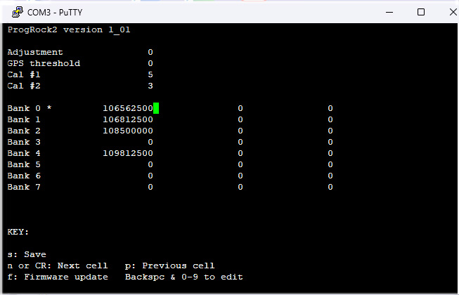
Best to program the ProgRock2 before soldering anything to it or mounting on the transmitter board. You cannot have the USB programming cable connected to the ProgRock2 board and computer at the same time its +V pad is connected to the transmitter board. Careful not to place the board on or near any thing conductive that could make contact with the exposed board. Make sure the USB micro / USB-A cable is a programming cable with all the wires vs. one that only has the +5 and ground for charging a device. Plugging in the ProgRock2 board into the computer com port with the USB cable will power it up and allow determining the COM Port number. Open PuTTY. Set the Session Window to 80 Columns and 24 Rows. Select Serial and COM Port number (it was 3 in my case). Then click Open. When the blank screen comes up, hit Return and the ProgRock2 programming screen should come up. Enter frequencies in Hz. For example, in Bank 2 in the first column (CLK 0 output) for transmitting on 434.0 MHz, enter the 108500000 frequency. Verify you have all 9 numbers, including trailing zeros, for a frequency in Hz in the 100 to 200 MHz range. All unused Bank cells in all 3 CLK (Clock) output columns need to be zero for no output if accidentily selected and to minimize current. The KEY to cursor movement is at the bottom of the screen. When you think you have all frequencies entered correctly, punch s to program the board and save. You can use a FM broadcast receiver placed near the board to verify success. The frequencies are kept in the boards non-volitile memory until written over later if you made a mistake or make changes, QRP Labs https://qrp-labs.com/progrock2.html |
|
|
Go to: The domain of this page is www.hamtv.com - copyright ©2026 W6ORG, all rights reserved. Webmaster contact is ATVinfo at hamtv dot com |
 P. C. Electronics Transmitter Crystal Frequencies: